
(VAT included) :
1,800.00 $ Earning
(VAT included) :
You must log in to add the product to your favorites.
Underground Imaging - Area Scanning
Version 2023
1. GENERAL FEATURES:
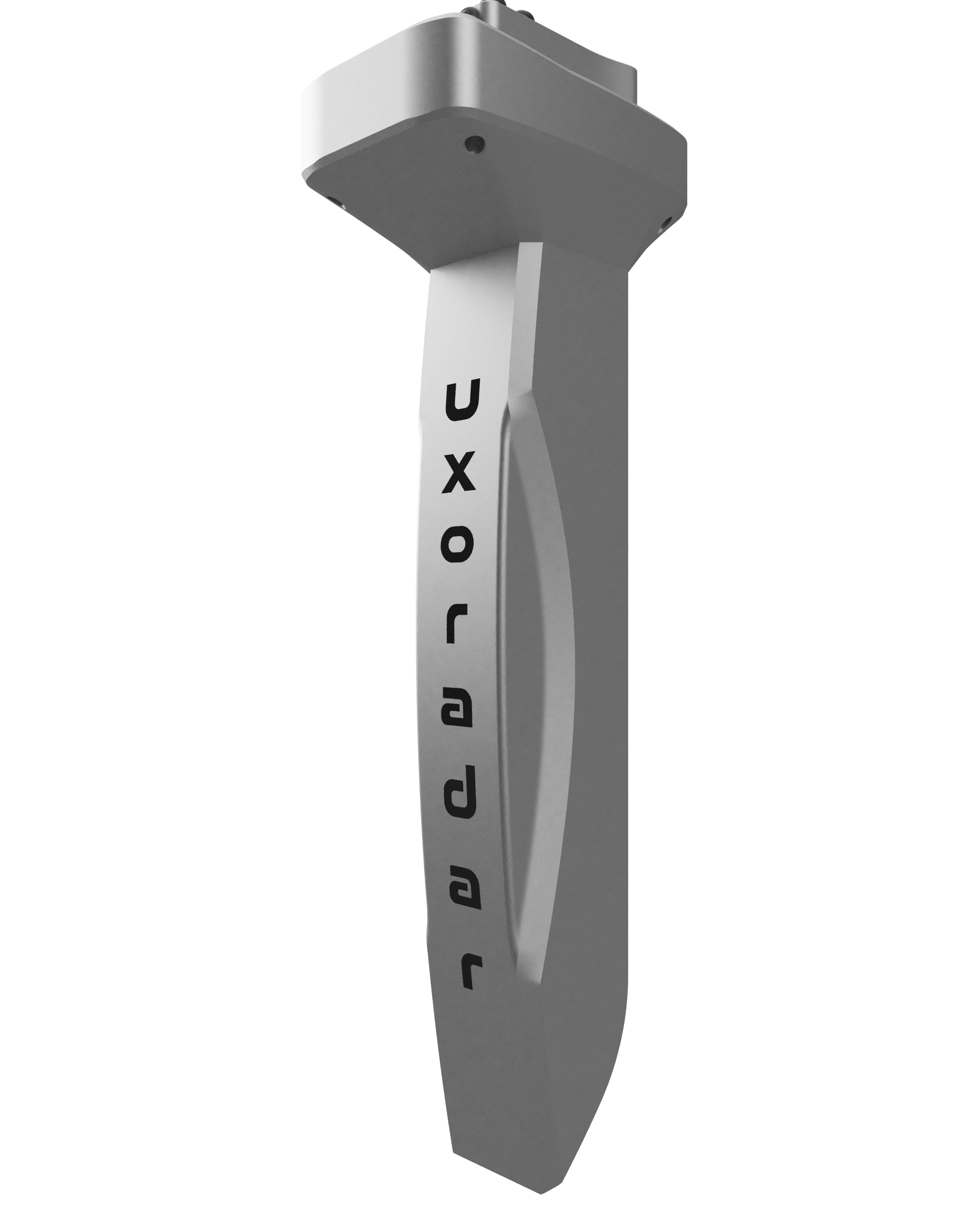
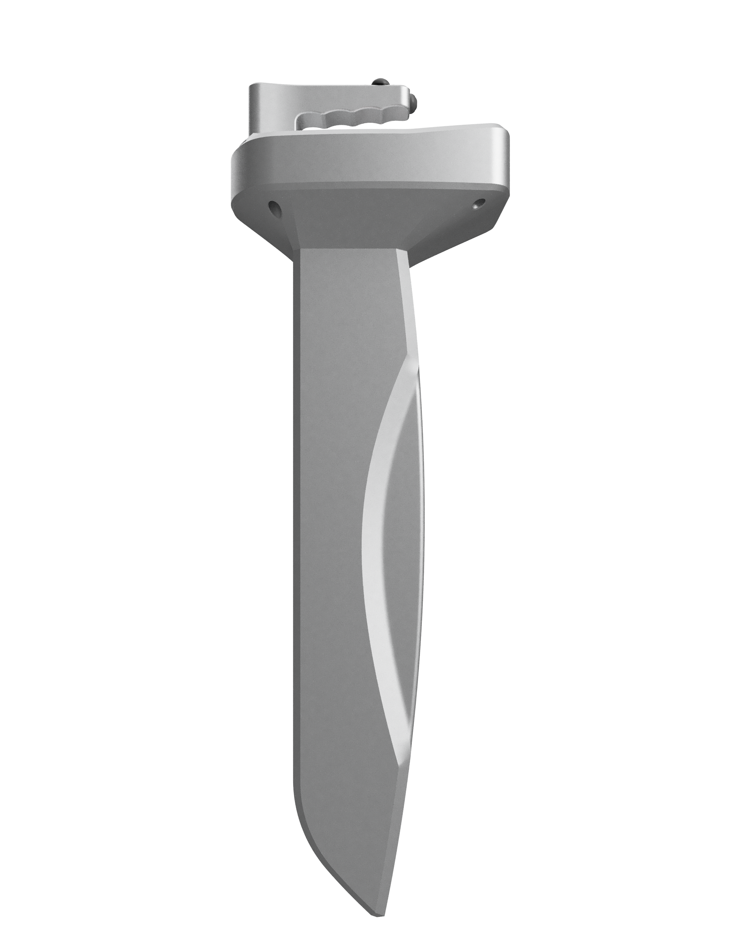
UXO Radar; It is an underground imaging device with an internal frequency generator. It is a device that can examine underground anomalies and visually display them in 2D and 3D with the help of magnetic field meter sensors. The shots taken with the help of its internal memory are designed to be stored in memory and viewed again later.
1.1. Frequency Generator: UXO Radar comes with 8 different frequency settings. There is also a manual fine tuning mode for each frequency setting. Signal transfer to the electrodes can be provided with the help of cables from two connectors on the device.
1.2. UWB Radar: With the help of ultra wideband radar, 2D display of underground anomalies can be provided. 1.3. Manual 3D Shooting: It has a mode that can store the shots taken to view the underground without the need for a computer, view them later and delete them when desired.
1.4. Automatic 3D Shooting: There is a 3D imaging mode that allows real-time shooting with the help of a computer.
1.5. Language, Sound, Brightness: It supports 4 different language options in total. It also includes features such as volume on/off adjustment and screen brightness control.
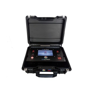
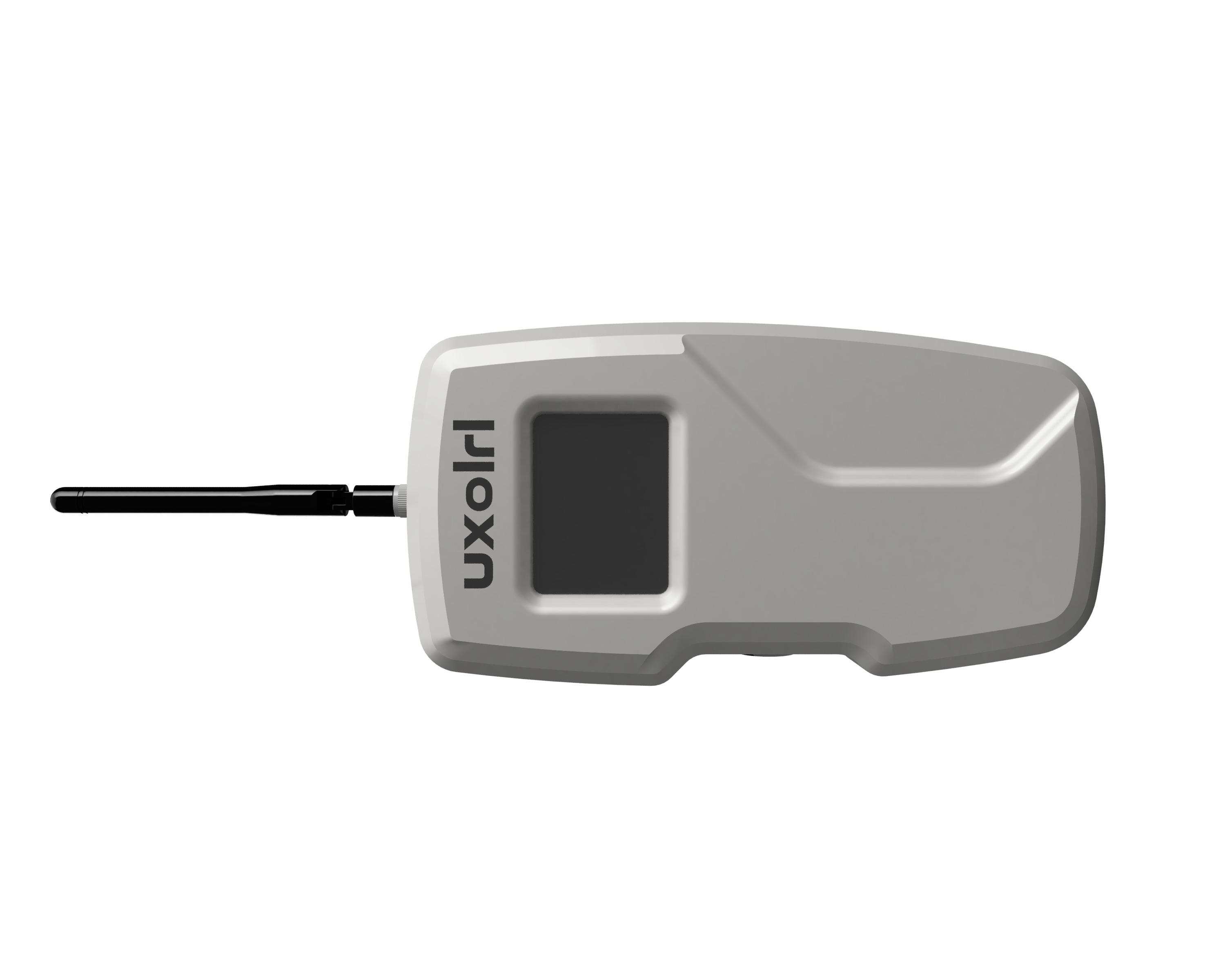
2. DEVICE INTRODUCTION:
UXO Radar device consists of a 4.3” TFT touch screen on the front panel, on-off switch, charging socket, signal outputs for the frequency generator and sampling, calibration, reset and back buttons.
Sampling button; This is the button used to take measurements during 3D imaging stages.
Calibration button; This is the button used to perform soil calibration in UWB Mode and 3D imaging stages.
Reset button; This is the button used to reset the ground calibration in UWB Mode and 3D imaging stages.
Back button; This is the button used to return to the previous screen while navigating within the menu.
3. DEVICE MENUS:
3.1. FIELD SCANNING:
You can generate and apply frequencies to your target object with the underground frequency generator integrated into the UXO Radar device. Drive the electrodes into the ground before starting the search. Then make the cable connections as shown in Figure 2.
Then, click on the AREA SCAN tab in the SETTINGS menu on your device.
On the screen that opens;
Target Type,
Target Frequency,
Manual Frequency Adjustment Bar and
There is a Set button.
The device is produced with frequencies specified for gold, silver, bronze, copper, phosphorus, iron, aluminum and jewellery. However, it also allows you to change frequencies manually. You can save the frequency by pulling the Manual Frequency Adjustment Bar to the right or left, setting it to the frequency you want, and then pressing the Set button. You can then continue your transaction.
3.2. ULTRA WIDEBAND RADAR
In ultra wideband technology (UWB), ultra-short pulses are used in transmission and reception, and the characteristic spectrum extends to a very wide frequency range.
Due to their low power spectral density, UWB systems can use frequency spectrums already reserved for other communication systems with minimal or no interference with other systems, and they are perceived as white noise by other radio frequency devices.
With the Ultra Wideband system, you can display the measured differences graphically on the screen. To use this mode, click on the UWB RADAR tab in the SETTINGS menu.
There are 4 main elements on the screen that opens.
Measurement value,
Calibration button,
Reset button to undo the calibration,
Graph table where measurement values are displayed.
When the screen is turned on, hold the device perpendicular to the ground (Figure 8) and press the Calibration button.
The calibration process is carried out with the calibration button in order to increase the sensitivity to the area to be measured. Calibration can be done frequently during the measurement phases. In this way, ground adjustment is made. Then the measurement process continues.
The measurements taken during the measurement are displayed as instantaneous values in the upper left corner and are also displayed as signals in the graphic table.
To cancel the calibration process, the Reset button can be pressed. The reset button is used to cancel the calibration process.
3.3. 3D MODE:
UXO RADAR 3D shooting mode consists of two different modes; MANUAL and LIVE SHOOTING mode.
Basically;
* The samples you take with MANUAL MODE are kept in the device memory. Management of captured samples can be done from the SHOOTINGS screen in the SETTINGS menu. Samples taken; By communicating the device with the computer, it can be transferred to the computer for 3D imaging. Unless you delete the footage from the device, those footage can be accessed. You do not need to have your computer with you to shoot. Samples are kept in memory and can be transferred to the computer whenever you want.
* To shoot with LIVE SHOOTING MODE, you must have your computer with you. The computer and the device work synchronously and the shooting is done. However, this shooting mode is not stored in the device memory. If you wish, you can save the footage to your computer after the shooting is completed.
3.3.1. Manual Mode:
Before you start shooting, you need to determine the location where you will shoot, the road to shoot and the number of steps to be taken on each road. Then, 3D shooting will be done manually with the path to be shot and the number of samples to be taken on each path.
3.3.1.2. Manual Shooting in Manual Mode:
After determining the number of roads for the area to be shot, it is adjusted using the up and down buttons in Figure 10. The Shot number is then set to save it in a memory that you know is previously empty. After the necessary adjustments are made, the measurement is started by pressing the Start button.
First, after completing the calibration process by pressing the Calibration button on the handle, you can start taking measurements with the measurement taking button. Measurements taken during shooting are shown in the lower right corner. It is also colored in accordance with the color separation in the 2D display mode on the right.
With this mode, the measurement take button must be pressed for each measurement. After the measurement is completed, you can transfer it to the computer with the Shot Number you saved from the SHOTS tab in the SETTINGS menu.
3.3.1.2. Auto Shooting in Manual Mode:
After determining the number of roads for the area to be shot, it is adjusted using the up and down buttons in Figure 12. The Shot number is then set to save it in a memory that you know is previously empty. After the necessary adjustments are made, the measurement is started by pressing the Start button.
First, after completing the calibration process by pressing the Calibration button on the handle, you can start taking measurements with the measurement taking button. Measurements taken during shooting are shown in the lower right corner. It is also colored in accordance with the color separation in the 2D display mode on the right.
To take measurements with this mode, simply pressing the measurement mode once is sufficient. Afterwards, it will automatically take measurements every 2 seconds. When you reach the left turning points, after taking the position, you need to press the measurement button again to continue taking measurements.
After the measurement is completed, you can transfer it to the computer with the Shot Number you saved from the SHOTS tab in the SETTINGS menu.
3.3.2. Live Shooting Mode:
Before you start shooting, you need to determine the location where you will shoot, the road to shoot and the number of steps to be taken on each road. Then, 3D shooting will be done automatically with the path to be shot and the number of samples to be taken on each path.
3.3.2.1. Auto Shooting in Live Capture Mode:
Since the shots taken with this mode are not saved in the memory, they are transferred directly to the computer. For this reason, the UXO Radar interface must be opened on the computer and the connection must be initiated. After determining the number of roads for the area to be shot, the measurement should be started by pressing the Start button.
First, after completing the calibration process by pressing the Calibration button on the handle, you can start taking measurements with the measurement taking button. Measurements taken during shooting are shown in the lower right corner. It is also colored in accordance with the color separation in the 2D display mode on the right.
To take measurements with this mode, simply pressing the measurement mode once is sufficient. Afterwards, it will automatically take measurements every 2 seconds. When you reach the left turning points, after taking the position, you need to press the measurement button again to continue taking measurements. Measurements can be displayed on the interface whenever the measurement button is pressed.
To take measurements with this mode, simply pressing the measurement mode once is sufficient. Afterwards, it will automatically take measurements every 2 seconds. When you reach the left turning points, after taking the position, you need to press the measurement button again to continue taking measurements. Measurements can be displayed on the interface whenever the measurement button is pressed.
3.3.2.2. Manual Shooting in Live Capture Mode:
Since the shots taken with this mode are not saved in the memory, they are transferred directly to the computer. For this reason, the UXO Radar interface must be opened on the computer and the connection must be initiated. After determining the number of roads for the area to be shot, the measurement should be started by pressing the Start button.
First, after completing the calibration process by pressing the Calibration button on the handle, you can start taking measurements with the measurement taking button. Measurements taken during shooting are shown in the lower right corner. It is also colored in accordance with the color separation in the 2D display mode on the right.
With this mode, the measurement take button must be pressed for each measurement. Measurements can be displayed on the interface whenever the measurement button is pressed.
With this mode, the measurement take button must be pressed for each measurement. Measurements can be displayed on the interface whenever the measurement button is pressed.
3.4. LANGUAGE SELECTION:
The device comes with a Turkish language option at startup, exclusively for Turkey.
If you want to change the language, you can change the language from the LANGUAGE SELECTION menu in the SETTINGS menu.
3.5. SHOOTING SETTINGS:
Memory space is reserved for 5 shots taken in manual mode with UXO Radar. Management of these 5 memory areas is done from this screen.
Measurements taken in manual mode can be managed from the SHOTS menu in the SETTINGS menu. Each area can be deleted individually or sent to a computer/tablet for 3D imaging.
3.6. SOUND & LIGHT:
This is the menu where you can mute the key sound during menu selection and transitions and adjust the screen brightness. It also includes hardware and software version numbers.
Sound and screen brightness management can be done from the SOUND & LIGHT menu in the SETTINGS menu.